
October 08, 2026 · Capital X Panel Designer · Electrical CAD
ECAD and MCAD Integration: How the Two Disciplines Work Together
Key Takeaways
- ECAD and MCAD serve different engineering functions. ECAD manages electrical connectivity and documentation, while MCAD manages physical geometry, placement, and fit.
- Integration connects the work without removing those responsibilities. Each discipline continues using the tools suited to its work while exchanging the design information the other team needs.
- Disconnected workflows create preventable problems. Manual data entry, BOM differences, revision gaps, and late discovery of space or clearance issues can all lead to rework.
- Effective ECAD-MCAD integration depends on structured data exchange, revision control, and clear ownership of design information.
- Capital™ X Panel Designer Advanced supports ECAD-MCAD workflows within the Siemens Xcelerator ecosystem, including data exchange with Designcenter Solid Edge and Designcenter X, plus BOM and project publishing to Teamcenter.
Introduction
Electrical and mechanical engineers rarely work on completely separate products.
Consider a control cabinet. The electrical engineer decides which contactors, terminals, PLC modules, protection devices, and connections the system needs. The mechanical engineer must then make sure those components fit on the mounting plate, stay within the enclosure, leave enough room for wiring ducts, and remain accessible for assembly and maintenance.
Both designs can be correct on their own and still fail when brought together.
That is the problem ECAD and MCAD integration is intended to solve. Instead of treating electrical and mechanical design as separate workflows that are reconciled near the end of a project, integration helps both teams exchange relevant design information throughout development.
If you first need a breakdown of the two disciplines, see our guide to MCAD and ECAD software and electromechanical co-design. This article focuses specifically on what happens when the two need to work together.
What Does ECAD and MCAD Integration Actually Mean?
ECAD-MCAD integration is the connection between electrical and mechanical design workflows so that information created in one engineering discipline can be used by the other without repeatedly rebuilding or manually interpreting it.
The two systems still perform different jobs:
- ECAD (Electrical Computer-Aided Design) handles schematics, device connectivity, wire numbers, terminals, panel components, electrical BOMs, and related documentation.
- MCAD (Mechanical Computer-Aided Design) handles 2D and 3D geometry, enclosures, mounting arrangements, dimensions, clearances, tolerances, and assemblies.
A useful way to separate them is:
ECAD defines what needs to connect. MCAD determines how those components physically fit.
Integration creates a controlled handoff between the two.
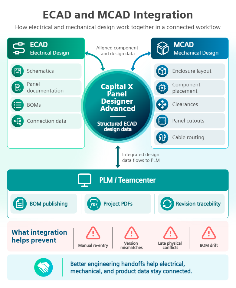
It does not necessarily mean electrical and mechanical engineers work inside the same application. A practical integration can instead allow each team to continue using discipline-specific software while passing structured component, connectivity, BOM, and design information between their systems.
Siemens similarly describes ECAD-MCAD co-design around data synchronization and collaboration between the two domains rather than replacing either discipline.
How Do ECAD and MCAD Work Together During Product Development?
ECAD and MCAD work best as an iterative engineering loop rather than a one-time file handoff.
A typical electromechanical workflow moves through four stages.
1. Electrical Engineers Define the System and Its Connections
The electrical team develops the schematic and defines how the system operates electrically.
Depending on the project, this can include:
- PLCs and I/O
- Contactors and relays
- Circuit protection
- Terminal blocks
- Power supplies
- Sensors
- Motors
- Wires and cables
- Device references
- Component specifications
Purpose-built electrical CAD software helps engineers manage this information as electrical design data rather than treating the schematic as a collection of lines and shapes.
Automation can also generate outputs such as wire lists, terminal information, connection reports, and BOMs directly from the design. For a closer look at these functions, see how electrical CAD automation handles schematic and documentation tasks.
2. Mechanical Engineers Validate the Physical Design
The mechanical team works with the physical constraints around those electrical components.
For a control panel, that could mean checking:
- Whether all devices fit on the mounting plate
- DIN rail capacity
- Wiring duct space
- Enclosure dimensions
- Component clearances
- Mounting-hole positions
- Cable routing space
- Access for installation and maintenance
- Interference between components
This is where electrical intent meets physical reality.
A schematic might show that an additional terminal block is required. Electrically, the change may be simple. Mechanically, those terminals could exceed the available DIN rail length and force a mounting plate or enclosure change.
Connecting the two workflows makes it easier to expose those conflicts while design decisions are still being made. Siemens describes this early mechanical validation as a core benefit of electromechanical co-design, including checks around mounting positions, clearances, panel cutouts, and cable routing feasibility.
3. ECAD and MCAD Exchange the Design Information Each Team Needs
The next step is the actual integration.
Instead of sending an electrical drawing to the mechanical team and asking them to manually recreate its component information, an integrated workflow transfers usable engineering data between applications.
Typical information can include:
| ECAD information relevant to MCAD | MCAD information relevant to electrical design |
| Component and device data | Available mounting space |
| Panel BOM information | Component placement |
| Connectivity information | Enclosure dimensions |
| Component references | Clearance restrictions |
| Panel layout intent | Mounting constraints |
| Electrical changes | Physical design changes |
The goal is not to move every piece of information between both systems. It is to transfer enough context for each discipline to make decisions based on the latest engineering definition.
That distinction matters. Sending PDFs or spreadsheets may communicate information, but somebody still has to interpret and re-enter it. Structured ECAD-MCAD data exchange reduces that repeated work and lowers the chance of one system drifting away from the other.
4. Both Teams Review Changes Before They Become Production Problems
ECAD-MCAD integration becomes especially valuable when designs change.
Suppose the electrical engineer replaces a component with a different model. Its electrical function might be identical, but its physical dimensions may be different.
Without a coordinated workflow, the mechanical engineer may continue designing around the original component.
Or the mechanical team might move several devices to solve a clearance problem without the electrical team immediately understanding how that affects wiring or cable routing.
A connected design process gives both disciplines a clearer way to review changes before approving the next revision.
For projects involving several engineers, suppliers, or reviewers, this technical connection should be supported by clear roles, review stages, and revision practices. Our guide to electrical schematic design collaboration best practices covers the teamwork side of that process.
What Happens When ECAD and MCAD Are Not Connected?
Separate ECAD and MCAD systems can still produce successful products. The problem arises when teams rely heavily on manual reconciliation to keep the systems aligned.
Several problems commonly follow.
Duplicate Data Entry Creates More Opportunities for Errors
If an electrical engineer creates the component data and somebody on the mechanical team manually enters it again, the same information now exists in two places.
Every component substitution, part-number change, or quantity adjustment then has to be repeated.
The more often information is re-entered, the easier it becomes for one version to become outdated.
Physical Conflicts Are Discovered Too Late
An electrical design can be functionally correct while creating an impossible physical layout.
Terminal strips may be too long. Cable ducts can interfere with components. A new device may need more clearance than expected.
Finding the problem digitally during design gives engineers more options. Finding it during panel assembly usually means changing something that has already been documented, approved, ordered, or manufactured.
Electrical and Mechanical BOMs Can Drift Apart
The BOM connects design work to procurement and production.
If the electrical team changes a component but mechanical documentation still references the previous part, purchasing and manufacturing may receive conflicting information.
Maintaining a reliable electrical Bill of Materials becomes much harder when engineering data has to be manually synchronized across disciplines.
Revision Control Becomes a Cross-Team Problem
Revision control inside one engineering system is only part of the problem.
Teams also need to know whether:
- The ECAD project matches the current MCAD assembly
- The BOM corresponds to the approved design
- Mechanical changes were reviewed by electrical engineering
- Electrical component changes were reflected mechanically
Without a shared revision process, each discipline can be working from a valid file that belongs to a different stage of the product.
What Does Good ECAD-MCAD Integration Require?
Connecting two software products alone does not create a good engineering workflow.
The integration also needs to preserve the information engineers use to make decisions.
Structured Engineering Data Instead of Manual Recreation
The strongest workflows pass useful design information between systems rather than depending entirely on screenshots, emails, spreadsheets, or redrawn component lists.
That reduces repetitive entry and gives the receiving engineer more usable context.
Clear Ownership of Electrical and Mechanical Data
Integration should not blur engineering responsibility.
Electrical engineers should continue controlling electrical connectivity and schematic intent. Mechanical engineers should control physical geometry and mechanical constraints.
The integration provides visibility across those boundaries without turning every change into a shared editing problem.
Consistent Component and BOM Information
Component identities, quantities, and revisions should stay aligned across the engineering workflow.
This becomes increasingly important once purchasing, manufacturing, or service teams begin using the same product information.
Revision Traceability
Engineers need to know what changed, which design version is current, and whether a change in one discipline affects the other.
This is especially useful on long-running projects where several revisions can occur before release.
Collaboration Throughout the Design Cycle
ECAD-MCAD integration works best when collaboration begins before the design is considered finished.
Waiting until the electrical design is complete before mechanical validation simply moves the coordination problem to a later stage.
Cloud-based engineering tools can also make that coordination easier for distributed teams because project access, comments, and revisions do not depend entirely on locally stored files. See the advantages of cloud-native electrical CAD for more on that workflow.
How PLM Extends ECAD-MCAD Integration Beyond the Design Team
ECAD and MCAD integration addresses communication between engineering disciplines. Product Lifecycle Management (PLM) adds another layer by managing how approved engineering information moves through the wider product lifecycle.
That matters because an engineering change can affect more than the CAD model.
A component update may also change:
- The BOM
- Procurement requirements
- Manufacturing documentation
- Product revisions
- Service records
- Configuration information
Connecting ECAD and MCAD information to PLM gives teams a more controlled way to manage these dependencies.
Within the Siemens Xcelerator ecosystem, Capital X Panel Designer Advanced can work with Teamcenter to extend ECAD data into broader product lifecycle workflows. Teams can publish electrical BOM data and project PDFs into Teamcenter, helping keep electrical design information, revisions, and product records better aligned across engineering functions. For a closer look at this connected workflow, see how Capital X Panel Designer Advanced bridges electrical and mechanical design.
The practical benefit is traceability: engineering data can remain connected to the broader product definition instead of stopping at the CAD handoff.
ECAD-MCAD Integration in a Control Panel Design Workflow
Consider a machine builder developing a new control cabinet.
The electrical engineer first creates the schematic, specifies PLC modules, protection devices, relays, terminals, and other components, then generates the associated device and BOM information.
The mechanical engineer needs those components to build the enclosure and mounting arrangement.
With a disconnected workflow, the process might look like this:
ECAD design → export spreadsheet/PDF → manual MCAD recreation → mechanical review → email corrections → ECAD changes → another export
Every handoff creates another opportunity for information to become outdated.
A connected workflow is closer to:
ECAD design → structured component data → MCAD validation → design review → controlled revision → updated product information
Neither engineer loses control of their discipline.
The difference is that they spend less time translating what the other team has already designed.
Where Capital X Panel Designer Advanced Fits Into ECAD-MCAD Integration
For engineering teams working within the Siemens ecosystem, Capital X Panel Designer Advanced supports electromechanical co-design by connecting electrical panel design with mechanical CAD and PLM workflows.
Capital X Panel Designer remains the ECAD environment where electrical engineers create schematics, panel documentation, BOMs, connection information, and other electrical design data.
The Advanced tier extends these electrical CAD capabilities with Siemens Xcelerator integrations for:
- Designcenter Solid Edge
- Designcenter X
- Teamcenter
Electrical schematic and component information can be exported for use in Designcenter Solid Edge or Designcenter X, reducing the need for mechanical engineers to manually recreate device information. Teams can also publish BOM data and project PDFs into Teamcenter to support product-data management and revision traceability.
These integrations build on Capital X Panel Designer's cloud-based electrical design collaboration features, including shared project access, permissions, version control, and real-time schematic collaboration.
The Advanced tier is most relevant for engineering teams whose electrical panel designs regularly interact with mechanical CAD or PLM. If projects remain primarily within electrical design, the Standard tier may already cover the required workflow. Advanced becomes more useful when electrical, mechanical, and product data need to stay coordinated across Designcenter Solid Edge, Designcenter X, or Teamcenter.
You can compare Capital X Panel Designer plans and Advanced integration features to see which tier fits your engineering workflow.
Conclusion: Better Electromechanical Design Starts With Better Engineering Handoffs
ECAD and MCAD will continue to solve different engineering problems.
The goal of integration is not to merge both disciplines into a single workflow. It is to keep the engineering information between them connected as the design changes.
Electrical engineers need confidence that specified components and connections can be accommodated mechanically. Mechanical engineers need accurate electrical component data before finalising layouts, enclosures, and assemblies. Engineering managers need both disciplines working from compatible revisions.
A well-connected ECAD-MCAD workflow moves these checks earlier in the design process, before inconsistencies become production changes or rework.
For teams already using Designcenter Solid Edge, Designcenter X, or Teamcenter, Capital X Panel Designer Advanced connects ECAD with Siemens mechanical CAD and PLM workflows, providing a practical way to improve coordination between electrical and mechanical engineering.
See ECAD-MCAD Integration in Practice
If you want to evaluate the workflow on an actual project, try Capital X Panel Designer Advanced free for 30 days. The trial includes its electromechanical co-design capabilities, although access to the corresponding Siemens Xcelerator applications is required to test their respective integrations.
FAQs About ECAD and MCAD Integration
1. When should an engineering team consider ECAD-MCAD integration?
ECAD-MCAD integration becomes useful when electrical changes regularly affect mechanical layouts, enclosure dimensions, component placement, or product documentation. It is especially relevant for teams that spend time manually transferring design information between electrical and mechanical systems or resolving cross-discipline issues late in a project.
Teams reaching this point can explore how Capital X Panel Designer Advanced supports electromechanical co-design.
2. What should teams prepare before integrating ECAD and MCAD workflows?
Start by defining which information needs to move between electrical and mechanical engineering, who owns each type of design data, and how revisions will be approved. Component naming, BOM structures, design standards, and change-control processes should also be consistent before introducing software integration.
For distributed teams, cloud-based electrical design collaboration can help keep project access, permissions, and design reviews within a shared workflow.
3. Do smaller engineering teams benefit from ECAD-MCAD integration?
Yes, if their projects involve frequent electrical-mechanical coordination. Company size matters less than the amount of manual handoff involved. A small machine builder producing control cabinets, for example, can benefit if engineers regularly have to reconcile component changes, mounting arrangements, BOMs, and project revisions between separate systems.
4. Do you need PLM software to use ECAD-MCAD integration?
No. ECAD and MCAD can exchange engineering information without a PLM system. PLM becomes more relevant when companies also need controlled product structures, revision history, BOM management, approvals, or engineering data that must remain traceable beyond the CAD teams.
Capital X Panel Designer Advanced adds Teamcenter integration for organisations that need this broader connection between electrical engineering and product lifecycle data.
5. Which Capital X Panel Designer tier is suitable if I do not need MCAD or PLM integration?
If your work is mainly electrical schematic and panel design, the Standard tier may already provide the functions you need. Advanced is aimed more specifically at teams that require connections with Designcenter Solid Edge, Designcenter X, or Teamcenter.
You can compare Capital X Panel Designer plans and integration features before deciding which tier fits your workflow.
6. Can teams test Capital X Panel Designer Advanced before adopting it?
Yes. Teams can try Capital X Panel Designer Advanced free for 30 days to evaluate its electrical design and electromechanical co-design capabilities against an existing workflow.
To test integrations with Designcenter Solid Edge, Designcenter X, or Teamcenter, access to the corresponding Siemens Xcelerator applications is also required.