
October 08, 2026 · Capital X Panel Designer · Electrical CAD
What Is ECAD? Electrical Computer-Aided Design Explained
Key Takeaways
- ECAD means Electrical Computer-Aided Design and covers software used to create and manage electrical or electronic designs.
- ECAD applications include electrical schematics, wiring diagrams, panel design, PCB layout, cable systems, control circuits, BOMs, and engineering documentation.
- ECAD and MCAD serve different engineering disciplines but need to exchange design information in electromechanical products.
- Connecting electrical design with manufacturing, procurement, and BOM workflows reduces manual data transfer and revision mismatches.
- PLM provides a common layer for controlling engineering data, revisions, changes, and downstream access.
- A digital thread keeps related electrical, mechanical, manufacturing, and lifecycle information connected as a product changes.
Introduction
ECAD stands for Electrical Computer-Aided Design. It refers to software engineers' use to create, develop, document, and manage electrical and electronic designs.
ECAD is a category of computer-aided engineering software focused on electrical and electronic design data, where engineers work with connected systems rather than static drawings. Unlike traditional CAD tools that primarily represent geometry, ECAD understands electrical relationships such as components, wires, terminals, nets, circuits, and device references.
This makes ECAD especially important in modern engineering, where products combine electrical, electronic, and mechanical systems. A design may function correctly on a schematic but still fail in practice if components do not fit inside an enclosure, cables interfere with mechanical parts, or electrical and mechanical teams work from different revisions.
Depending on the engineering discipline, ECAD software may be used for electrical schematics, control systems, wiring diagrams, cable and harness designs, printed circuit boards (PCBs), panel layouts, component data, and bills of materials (BOMs). Some ECAD platforms also include electrical verification, simulation, design-rule checking, and integration with mechanical CAD or product lifecycle management systems.
As a result, modern ECAD is no longer a standalone design tool. It increasingly connects with MCAD, manufacturing, procurement, BOM management, and PLM to support a fully integrated engineering workflow.
IEEE research on electrical, mechanical, and thermal design integration highlights the need for data exchange between ECAD, MCAD, and physical design analysis tools, reflecting the broader shift from isolated electrical design toward connected multidisciplinary engineering workflows.
What Is ECAD?
While ECAD is often used as a general term, it represents a broad range of electrical and electronic design applications.
ECAD software allows engineers to model electrical systems as intelligent, connected data rather than simple drawings. A change to a component in a schematic can automatically update wiring references, terminal information, reports, and BOM data.
The exact meaning of ECAD depends on the engineering field, but it commonly includes:
- Electrical schematic and control system design
- Electrical panel and cabinet design
- Wiring and cable documentation
- Wire harness engineering
- PCB schematic capture and board layout
- Electronic component management
- Electrical design validation and analysis
This makes ECAD broader than any single type of electrical design software.
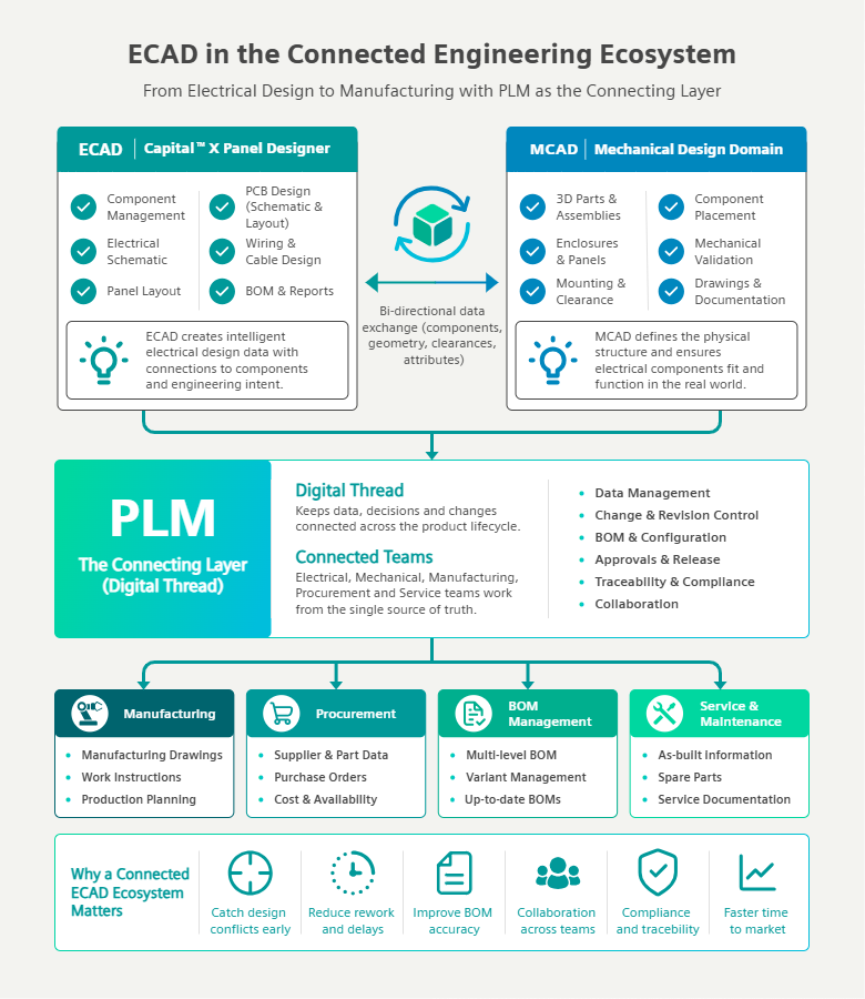
How ECAD fits into a connected engineering workflow:
ECAD and MCAD create discipline-specific engineering data, while PLM and the digital thread connect that information with BOM management, procurement, manufacturing, and downstream teams.
What Does ECAD Software Do?
ECAD software helps engineers turn electrical requirements into design data that can be reviewed, manufactured, installed, maintained, and updated throughout the product lifecycle.
Electrical schematic design defines how components connect
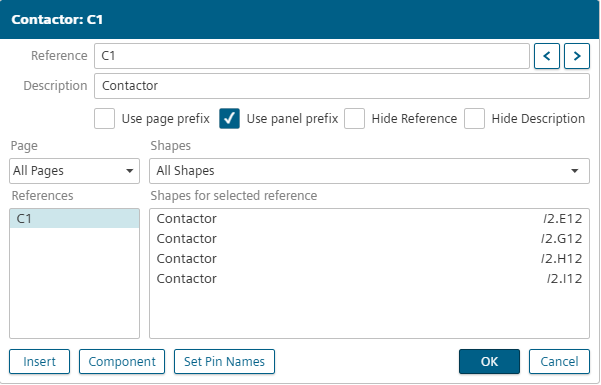
Electrical engineers use ECAD software to create schematic diagrams showing connections between switches, relays, PLCs, terminals, motors, sensors, power supplies, and other components.
Modern ECAD tools can automate wire numbering, component tagging, cross-referencing, terminal generation, circuit reuse, and documentation.
For example, Capital™ X Panel Designer supports schematic automation including Autowiring, automatic symbol and wire numbering, real-time cross-references, terminal generation, panel layouts, and BOM reporting.
PCB ECAD tools turn electronic circuits into physical board layouts
In electronics engineering, ECAD is commonly used for schematic capture and printed circuit board design.
Engineers define electronic components and their connections, then move into PCB layout where traces, layers, vias, and components must meet physical and electrical constraints.
This represents a different design problem from industrial electrical panel or control system ECAD, even though both fall under the ECAD umbrella.
ECAD can support electrical analysis and design verification
Some ECAD systems include simulation and analysis capabilities such as circuit simulation, electrical rule checking, signal analysis, power analysis, and design validation.
These tools help engineers identify issues before physical prototypes or production. However, simulation is not universal and depends on the ECAD category and application.
ECAD creates engineering documentation for downstream teams
ECAD software also generates the documentation required for manufacturing, procurement, and maintenance, including:
- Bills of materials
- Wire lists
- Cable schedules
- Terminal plans
- Component lists
- Panel layouts
- Connection reports
- Manufacturing drawings
- Engineering revision records
Capital X Panel Designer electrical schematic software can generate these outputs directly from electrical schematic data.
What Are the Main Benefits of ECAD Software?
The main benefit of ECAD is that it provides design intelligence rather than simple drawing capability.
Less repetitive electrical design work
Automation reduces manual tasks such as numbering, tagging, cross-referencing, and documentation updates.
Better consistency between drawings and engineering data
Because electrical objects carry data, changes automatically propagate into related documentation.
Earlier detection of design conflicts
ECAD–MCAD collaboration helps identify issues such as clearance problems, mounting conflicts, and cable routing issues earlier in the design process.
More reliable engineering handoffs
Connected ECAD workflows reduce the need for manual reconciliation between drawings, spreadsheets, and BOMs, improving consistency across engineering and manufacturing teams.
Where Is ECAD Software Used?
ECAD is used anywhere electrical or electronic systems are part of a product or installation.
Common applications include:
- Industrial automation
- Control panel engineering
- Electronics and PCB design
- Automotive and transportation systems
- Machinery and equipment
- Aerospace systems
- Energy and utilities
- Manufacturing systems
ECAD requirements vary by application, whether engineers are designing schematics, control panels, wire harnesses, or PCBs. Explore the most common industries using electrical CAD software and how each applies ECAD in practice.
What Is the Difference Between ECAD and MCAD?
ECAD focuses on electrical and electronic systems, while MCAD focuses on physical and mechanical design.
| ECAD | MCAD |
| Electrical connections | Physical geometry |
| Schematics and wiring | Parts and assemblies |
| Electrical components | Mechanical components |
| Electrical BOMs | Mechanical BOMs |
| Electrical connectivity | Physical fit and structure |
Both are required in electromechanical products such as control panels, where electrical function and physical design must align. For a deeper look at how both systems connect across the engineering process, read our complete guide to MCAD and ECAD software for electromechanical co-design.
Why Do ECAD and MCAD Need to Work Together?
Electrical and mechanical design decisions directly affect each other.
A change in an electrical component can impact:
- Dimensions
- Heat output
- Mounting requirements
- Connector positions
- Cable routing
- Enclosure space
- BOM structure
Without integration, these changes may not be reflected across teams until late-stage design or manufacturing.
Integrated ECAD–MCAD workflows help maintain alignment by enabling shared design context across disciplines. To understand how information moves between both engineering environments, learn more about ECAD and MCAD integration and how the two disciplines work together.
ECAD Must Also Connect With Manufacturing, Procurement and BOM Management
ECAD–MCAD integration alone is not enough.
Once a design is complete, manufacturing and procurement require accurate and consistent data. A single component change can affect schematics, mechanical layouts, BOMs, supplier data, and production instructions.
Without connected systems, each department may maintain separate versions of the same data, leading to inconsistencies.
Connecting ECAD with downstream workflows ensures engineering, manufacturing, and procurement all work from aligned product information.
How Does PLM Connect ECAD With the Rest of Engineering?
Product Lifecycle Management (PLM) provides a controlled system for managing product data across engineering and downstream teams.
PLM manages:
- Design revisions
- Engineering changes
- Product structures
- BOMs
- Components
- Approvals
- Manufacturing data
- Traceability
Instead of replacing ECAD or MCAD tools, PLM connects them by managing the data they produce.
What Is the Digital Thread in ECAD?
A digital thread connects engineering data across tools, teams, and lifecycle stages.
An electrical component may exist in:
- ECAD schematic
- Panel or PCB layout
- MCAD assembly
- BOM system
- Procurement records
- Manufacturing documentation
- Released product configuration
Without a digital thread, each becomes a separate copy. With it, all remain connected and traceable throughout the product lifecycle.
Which ECAD Tools Are Commonly Used?
ECAD tools vary depending on engineering needs:
1. Electrical schematic and panel design ECAD
Focuses on control systems, wiring, panels, and documentation.
2. PCB design ECAD
Focuses on electronic circuit design and board layout.
3. Harness and electrical systems ECAD
Focuses on wire harnesses, cable systems, and electrical distribution.
What Features Should You Look for in ECAD Software?
Key features depend on application but often include:
- Intelligent symbols
- Automatic numbering
- Cross-referencing
- Circuit reuse
- Terminal management
- Panel layout tools
- BOM generation
- Version control
- Collaboration tools
- Component libraries
- MCAD integration
- PLM connectivity
The right ECAD features depend on the type of electrical work your team handles and how the software fits into wider engineering workflows. For a more detailed evaluation framework, explore the important factors to consider when choosing electrical CAD software.
How Capital X Panel Designer Connects ECAD With MCAD and PLM
Capital X Panel Designer is Siemens’ ECAD solution for schematic and panel design, combining electrical design automation, documentation, and collaborative engineering in one environment.
For teams working across electrical and mechanical disciplines, Capital X Panel Designer Advanced connects ECAD with MCAD and PLM workflows through Designcenter Solid Edge, Designcenter X, and Teamcenter PLM.
This gives electrical and mechanical teams better visibility into shared engineering data as designs change. For a broader look at the workflow, read our complete guide to MCAD and ECAD software for electromechanical co-design, including how both disciplines coordinate design data across the development process.
Conclusion: ECAD Is Part of a Connected Engineering Workflow
ECAD enables engineers to design and manage electrical systems using intelligent data rather than static drawings alone.
As products bring together more electrical, electronic, and mechanical components, that data also needs to stay aligned with mechanical design, manufacturing, procurement, BOM management, and PLM.
Connecting ECAD with MCAD and PLM helps teams maintain consistent engineering information, trace design changes, and reduce gaps between design and downstream execution.
Want to see how this works in an actual engineering workflow? Try Capital X Panel Designer Advanced free for 30 days and evaluate how ECAD, MCAD, and PLM integration fits into your current process.
Frequently Asked Questions About ECAD
1. Who typically uses ECAD software?
ECAD software is commonly used by electrical engineers, electronics engineers, control panel designers, automation engineers, PCB designers, wire harness engineers, and teams responsible for electrical documentation. The right platform depends on whether the work involves schematics, panel design, harnesses, PCBs, or wider electrical systems.
2. Can ECAD software replace general-purpose CAD software for electrical design?
For electrical engineering work, ECAD software is usually more suitable because it understands electrical components, connections, references, and engineering data. General-purpose CAD can create electrical drawings, but tasks such as wire numbering, cross-referencing, terminal documentation, and report generation often require more manual work.
For teams focused on schematic and panel design, Capital X Panel Designer electrical schematic software provides electrical-specific design and automation capabilities rather than general drafting tools.
3. What should companies consider before moving to a new ECAD platform?
Companies should review their current design process, automation needs, component libraries, reporting requirements, collaboration workflows, MCAD connections, PLM compatibility, and migration effort. The aim should be to improve the full engineering workflow rather than simply replace one drawing tool with another.
Teams evaluating their options can also compare how Capital X Panel Designer supports modern electrical design workflows across schematic creation, panel design, automation, documentation, and collaboration.
4. How does ECAD software help reduce engineering errors?
ECAD software keeps related electrical information connected throughout the design. When engineers change components, wires, references, or device information, associated documentation can be updated more consistently, reducing mismatched drawings and outdated project data.
5. Can ECAD software support multiple engineers working on the same project?
Yes. Cloud-based ECAD software such as Capital X Panel Designer can provide shared project access, controlled permissions, version management, and collaborative review features. This helps distributed teams, contractors, and external reviewers work from the same project data without relying on separate local files.
6. When should a team consider integrating ECAD with MCAD and PLM?
Integration becomes more valuable when electrical changes regularly affect mechanical design, BOMs, procurement, or manufacturing. Teams working on control panels, machinery, electromechanical products, or multi-discipline projects can benefit from reducing manual data transfer between engineering systems.
For teams already working within the Siemens ecosystem, Capital X Panel Designer Advanced connects ECAD with MCAD and PLM workflows through Designcenter Solid Edge, Designcenter X, and Teamcenter.
7. Can existing electrical designs be reused in ECAD software?
Many ECAD platforms support reusable circuits, schematic pages, templates, or design modules. Engineers can build from proven designs instead of recreating common motor circuits, control circuits, or panel sections for every project, helping reduce repetitive work and improve consistency.
8. Is cloud-based ECAD suitable for professional engineering teams?
Yes, provided the platform meets the team’s requirements for security, access control, collaboration, performance, and integration. Cloud-native ECAD can be especially useful for teams working across locations because users can access shared projects without maintaining separate desktop installations and project files.