May 12, 2020 · Electra E8 · Visio
10 Visio Tips for the Electra E8 User
We are now part of Siemens’ family. Electra Cloud is now Capital Electra X and Electra E9 is now Capital Electra 2210.
We have been Visio users for a long time and it's easy to forget that despite being easy to use, new Visio users may need to spend some time in Visio to familiarize themselves with this environment.
So here are 10 tips that will hopefully speed things up and get you productive quickly.
1. How to pan and zoom easily.
If you are using Visio 2003/2007, we like to customize the toolbar with 3 additional icons that let us zoom quickly. Right click on the toolbar, click customize, then click on "View" and drag and drop "Zoom In", "Zoom Out" and "Whole Page" onto your toolbar. These 3 icons lets us zoom in, out and look at the entire page with just a click of the mouse. 
If you are using Visio 2010, these 3 icons are displayed on the lower right corner of your window automatically. 
If you want even easier pan and zoom, click on View menu and select "Pan and Zoom" (Visio 2010: View tab | Task Panes | Pan and Zoom). This window can be dragged to be floating or glued to the left or right of your screen and can be pretty useful. 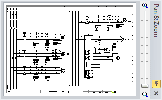
2. How to draw and measure with specific dimensions.
To draw a line/rectangle/circle with specific dimensions, open the size and position window. Under View menu, click on size and position (Visio 2010: View tab | Task Panes | Size and Position). 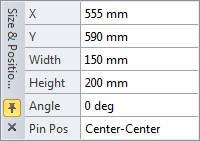
In the width and height fields, type in your dimensions in major units (e.g.: 12in, 13 in, 14 km, etc) and Visio will understand your units and size accordingly, taking into account your current settings for page scale and page measurement units. If you wanted to draw a line slanted at a particular angle, just draw a straight line and use the size and position window to key in your required angle
If you are using layout shapes in the stencils provided by Electra, right click on these shapes to set exact dimensions. In addition, using the Electra menu "Manage Components" or "Generate Layout" would also allow you to do the same 
To measure dimensions, drag and drop the 3 measurement shapes shown at left, and drag on their yellow handles to measure and display dimensions. Right click on these shapes to change measurement units into inches or cm. 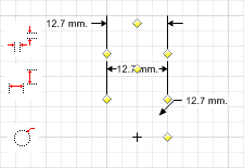
3. How to draw dotted, dashed lines and arrows.
Draw a normal line, make sure it is selected, then click on the line icon or icons shown at bottom to change line thickness (weight), dashes or arrows 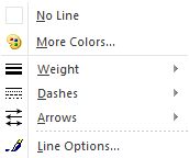
The same applies for wires in Electra, make sure a wire is selected and then click on these icons to change the wire from its default solid line to dashes or to any color you fancy.
4. How to set and use layers.
Many Visio users might not know that Visio support layers and in normal usage, layering might not be needed, but if you do need it, click on the View menu | Layer Properties (Visio 2010: Home tab | Layers | Layer Properties) to access layers.
In Electra, pin names and descriptions are separated into their own layers, so that their properties can be easily changed globally, as shown below: 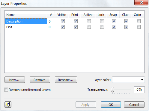
You can assign all descriptions to be shown in a color of your own choosing, or have it shown but not printed and vice versa. The same applies for pin names. If required, you can make your own layers and assign your symbols and text onto your custom layers.
5. How do draw a triangle or hexagon.
To draw a triangle, click on the Line tool, then click and drag to draw a straight line (as shown at bottom). The blue handle with white fill shows the beginning of the line while the blue handle with blue fill shows the end of the line. Click and drag on the end point of the first line, to make a second line and Visio will automatically join the 2 lines. Repeat the same for the 3rd line and Visio will automatically close the 3 lines to make a triangle and automatically fill it with white color. The same applies for drawing a hexagon or for any other multi-sided shapes. 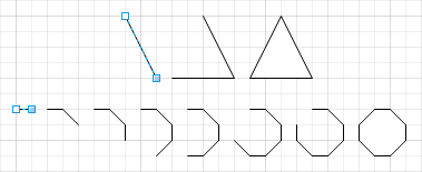
6. How to draw a curved line.
Click on the Freeform tool, then click and drag to make an arc. Hover your mouse over this arc, and Visio will display additional handles. Drag on the round handle to bend the curve to your requirements. 
7. How to flip and rotate shapes.
If you are using older versions of Visio, just right click to rotate or flip a shape. If you're using Visio 2010, you will need to right click on your ribbon and select customize, then find the rotate tool and add it into your ribbon. The rotate tool will let you flip a shape in addition to rotating it, which is not very user friendly (hey Microsoft, are you listening?) by any means. 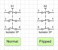
Click and select any shape you wanted to rotate/flip, and then click on the rotate button to rotate/flip.
Symbols in Electra were made with their pin names from left to right and top to bottom. If for any reason you require that these pin names appear otherwise (as shown above), you can do a flip on the symbol, and both the connection points and pin names will be flipped to the desired position.
8. How to change a shape's stacking order.
Sometimes you might want to make shapes that is stacked on top of one another, as shown at left. The top image shows the triangle on top, square in the middle and circle at the bottom of the stack. All of them are given 50% transparency for illustration purposes.
Right click on any shape and select "Send to Back" or "Bring to Front" to rearrange their stacking order.
The bottom image shows the triangle being "Send to Back" and thus we have now the square on top, circle in the middle and triangle at the bottom of the stack. 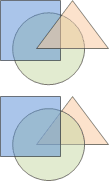
9. How to format text block in shapes.
All shapes in Visio can have text attached (even though the text might be blank), and only a single text can be attached to a single shape. To have multiple text, you would need to group multiple shapes in a group, where each shape in a group can then have their own text. 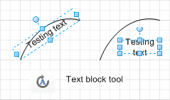
As shown in the image at above, by default, Visio will format the text block accordingly, for rectangles, the text block will fill the entire rectangle, for lines, the text will follow the curve of the line in question. If you need to change the appearance of the text, click on the shape and then click on the text block tool and then drag on the blue handles. You will be able to resize the text block in addition to repositioning the text to wherever you require.
10. What are connection points and why is it important.
In Visio, you are allowed to connect one shape to another and Visio will manage your connection by displaying a line between the 2 shapes using the shortest path possible.
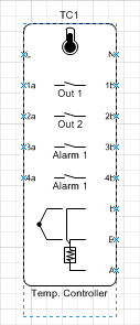
In electrical CAD drawings, Electra would require that you connect a wire only to connection points (as shown at left with blue 'x' at the edge of the symbol). This is because only by connecting to a connection point, would Electra be able to know that you have connected a wire to a terminal on your symbol and be able to generate a connections (from/to) listing properly. 